
Tamás Fábián said:
Hello Ray,
the absolute maximum value is 11.8 Volts. This comes from the datasheet of the integrated circuit we use for driving the outputs (DRV8833). The safe operating limit is 10.8 for the same IC.
Having said that, we managed to overvolt SBricks up to 14 volts and never damaged a single one. However, do not take this as a recommendation. It's a bit like overclocking / overvolting CPUs and memory modules in a PC. Be aware that overvolting your SBrick beyond the absolute maximum voids your warranty.
What you can do is:
- Play safe, and don't run the SBrick over 10.8V
- Accept some extra heating and reduced safety margin, and go near the absolute maximum limit of 11.8V
- Accept the chance of immediately and permanently damage or severely reduce the lifespan of your SBrick, and run it over the absolute maximum of 11.8V.
- Use a 3-cell Lithium Iron Phospate (LiFePo4) battery. With a maximum cell voltage of 3.65V it just barely goes over the recommended operating limit of 10.8V, and stays well below the absolute maximum.
Ray Simon said:
Thanks Lenard! I have a follow up question: Is it safe to connect a fully charged three-cell LiPo directly to the SBRICK Plus? I'm sure when the battery levels off to nominal voltage of 11.1V it is safe. The question is if the initial voltage of 12.6V will harm the SBRICK.
I would like to use my hobby-grade 3S LiPo batteries with the SBRICK Plus. These are standard three-cell LiPo used for RC cars, airplanes, helicopters, etc. The behavior of these batteries is that at full charge, the voltage is 12.6V without load. After load is applied and some current draw, the voltage drops and levels off to "operating" or "nominal" voltage which is 11.1V.
I have been researching other options to use my 3S LiPo batteries and you can get a DC-to-DC mini voltage regulator, but generally the output must be at least 1.5V below the input voltage, which means it would need to be set to about 9V to be safe to handle the LiPo as the voltage drops while it is discharged. This is possible but requires more complexity and equipment. It would be much simpler if we can connect the LiPo directly to the SBRICK.
Thanks for your support!
A simple solution for using the ubiquitous 3C LiPo batteries is to wire one (or better two) standard silicon diodes in series with the sBrick. Each one will drop between 0.5V and 1V, depending on load conditions. At the same time, they will protect your sBrick from accidental voltage reversals. I am cuurently using one 1N5406. It is rated at 3A, which is good enough for my creations, and gives me an idle voltage of 12.0V at the input of the sBrick. Take another one to be on the save side (i.e. within specs).
Nikolaus


Buck-Boost-Converter:
https://www.ebay.de/itm/Auto-Step-up-down-Buck-Boost-DC-DC-Schalt-Spannungregler-einstellbar-1-25V-30V-/201200556338?_trksid=p2385738.m4383.l4275.c10
There are a lot similar offers on ebay, but most of them shipping from China.
Just search for "LM2577" or "XL6009" and "Buck-Boost".
It drives up to 2A, which is enough for 2 L-Motors and a Servo-Motor in a Car-Model like Lego-42077 or Madoca-BlueLightning.
Switch:
Just a simple On/off-Switch that drives 2A.
The kind of the switch depends where you want to integrate it into the model.
I used this one to integrate it into a flat Lego-Panel:
https://www.ebay.de/itm/Eledis-Wippschalter-MR519-0F222-250-V-AC-3-A-1-x-Aus-Ein-rastend-1-St/362970929781?epid=1904193168&hash=item5482c0da75:g:mQYAAOSwGylelsN2
or for example such one:
https://www.conrad.de/de/p/tru-components-tc-r13-603c-05-schiebeschalter-250-v-ac-3-a-1-x-ein-ein-1-1587768.html
Hi,
Can someone please share the links for Lipo, charger, switch, Buck-boost converter? I saw there for each element there are tons of options available. I saw some video for dc-dc buck boost converter and it could not go more than 1A. https://www.youtube.com/watch?v=IFiupEP_vB8
So if someone can please specify, that would be really helpful..
I am using normal 3S LiPos in combination with an adjustable DC-DC Buck-Boost converter.
This kind of converter is a combination of Step-Down and Step-Up converter.
You can buy such devices for ex. based on circuits LM2577 or XL6009 at E-Bay.
I adjusted the converter to output voltage of 11,1V. I am using a 2A-version of such a converter to drive 2L-Motors and Servo-Motor.
It is very important to add a switch between LiPo-battery and converter, because the converter drains the battery by the time. Without a switch, the battery is deloaded completly after a few days without using the Lego-model. And completly deloaded LiPos get damaged.
Best regards, Andreas.

Hello Ray,
the absolute maximum value is 11.8 Volts. This comes from the datasheet of the integrated circuit we use for driving the outputs (DRV8833). The safe operating limit is 10.8 for the same IC.
Having said that, we managed to overvolt SBricks up to 14 volts and never damaged a single one. However, do not take this as a recommendation. It's a bit like overclocking / overvolting CPUs and memory modules in a PC. Be aware that overvolting your SBrick beyond the absolute maximum voids your warranty.
What you can do is:
Ray Simon said:
Thanks Lenard! I have a follow up question: Is it safe to connect a fully charged three-cell LiPo directly to the SBRICK Plus? I'm sure when the battery levels off to nominal voltage of 11.1V it is safe. The question is if the initial voltage of 12.6V will harm the SBRICK.
I would like to use my hobby-grade 3S LiPo batteries with the SBRICK Plus. These are standard three-cell LiPo used for RC cars, airplanes, helicopters, etc. The behavior of these batteries is that at full charge, the voltage is 12.6V without load. After load is applied and some current draw, the voltage drops and levels off to "operating" or "nominal" voltage which is 11.1V.
I have been researching other options to use my 3S LiPo batteries and you can get a DC-to-DC mini voltage regulator, but generally the output must be at least 1.5V below the input voltage, which means it would need to be set to about 9V to be safe to handle the LiPo as the voltage drops while it is discharged. This is possible but requires more complexity and equipment. It would be much simpler if we can connect the LiPo directly to the SBRICK.
Thanks for your support!

Ray Simon said:
What is the Max Current for the SBrick plus? I see this question was posted four years ago, but maybe we have better information today and also maybe there has been updates to the hardware in SBrick.
Has anyone measured peak current per channel, or for all four channels?
Also what is max voltage input for SBrick Plus? Thanks.
Hi, you can use 12V lipo with SBrick Plus.
What is the Max Current for the SBrick plus? I see this question was posted four years ago, but maybe we have better information today and also maybe there has been updates to the hardware in SBrick.
Has anyone measured peak current per channel, or for all four channels?
Also what is max voltage input for SBrick Plus? Thanks.

I'm working on my huge backlog... so it arrived the time to upload some photos of my cable as promised before. ;)


As you ccan see I've used a cable kit I had prepared before for my PF experiments, so it came handy also here! :)
The 10 Ohm resistance goes on C1 or C2 and the I use the shunt cable to coneect C2 or C1. Because the shunt cable is a pair I've also connected the GND but that's not required.
The resistor terminals are just bent and inserted into the terminal receptacles. No soldering was needed this time. :D
Thank you Jorge, I just wanted to clarify things a bit :)
I'd only like to add that the resistors limit the inrush current, the big current surge that occurs if you try to turn on a M motor. The resistor hack was used with the prototypes to correct the mismatch between the motor driver circuit and the motors. The inrush current caused the ICs to turn themselves off to avoid damage. Unfortunately by the time they turned themselves on again, the filter capacitors you need to charge to start the motor were flat again. This repeating cycle resulted in no movement, just a whimp shining sound about 1KHz as the ICs were turning themselves off and on again a thousand times per second.

No need to program the SBrick. It's the same as with the LEGO Power Functions IR, you get more voltage without the current limitation of the LEGO Power Functions battery (well, perhaps the IR has also some current limitation, don't know).
But watchout, don't use 11 Volt, you might burn the SBrick internal circuits. Play safely, keep it under 10.8. And use a LiPo with internal overcurrent protection... LiPo could be very explosive.
And with production SBrick you don't need the hacked cable at all, normal LEGO Power Functions cables will work fine.

Yes, I made it myself!
It happens that sometimes I play with PF to power other devices, or like to play with PF signals in my experiments. So I have prepared a few cables with single pin conectors soldered to each wire and insulated. So I can do what I want anytime.
It also happens that I had some old resistors in the garage, and I managed to find a 10 Ohm one.
The PF motors are powered from the C1/C2 wires, hence I just needed two half cables and to connect the resistor in series with C1 or C2 wires. The way I had it prepared, I even didn't have to solder anything. Just inserted each of the two resistor terminals into the respectiver connectors.
One of these days I'll take a photo and put it here for your reference.
You make yourself, easy: get a Power Functions extension cord, make a cut on the C2 or C1 wire, peel the isolator at each cut and solder a 10 Ohm resistor.
- for the pinouts see this image from Phlo's website:
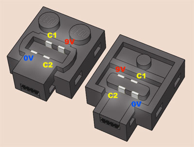
The 10 Ohm resistor limits the initial current (when the capacitors are being charged) to 9 Volt/10 Ohm=900 mA. But after a few miliseconds, when the capacitors get charged, current will flow through just the resistor and the motor and will drop to almost the «nominal» value of the motor.
You just have to choose a resistor capable to handle enough heat - let's suppose you will use the motor at 300 mA: that will make the resistor dissipate 10 Ohm x (0.3 A)² = 0.9 Watt so choose a 10 Ohm / 1 W [or bigger]. If you don't have that nearby you can use normal 1/4 Watt resistors in serial (like 4x resistors of 2.7 Ohm) or parallel (like 4x resistors of 39 Ohm).
:D Well, I have a story about that!
As I've said above, we had quite a lot of trouble with M motors. The problem is with their BIG filter capacitors. They need to be charged very quickly, and that means a HUGE current, and the driver ICs are just shutting down.
Before we've managed to solve the issue, we needed to somehow work around the situation. No model was able to work with M motors, so I decided to cut a few PF cables and install a 1Ohm resitor to limit inrush current.
The motors finally worked OK, and we could buld the old protorypes into models with M motors, and make awsome videos.
But.
We consumed a crateload of PF cables for various reasons, and there were a constant shortage of them.
Then Zsolt Szrapkó, our great web programmer got bitten by the LEGO MOC bug, and started to work on his super car, with the awsome RC motor and custom LiPo power supply.
"Of course" no extension calbes could be found, so I gave him a 1Ohm-hacked cable with the notice that the motor might run a bit slower or the resistor might get a bit warm.
We started to drive the model and it wasn't powerless at all, we had a lot of fun with it, until we discovered that the resistor was charred and smoking. :D A quick calculation showed that we tried to pump through it about four times the current it was rated for, so no surprise it changed it's colour a bit :)
The fresh prototypes of course don't need such dirty tricks to get M motors going, the new and final version could reliably drive 3 M motors on one channel.
Due to the modifications each channel can supply up to 3 amps of current. Note that this probably won't mean that the SBrick will actually be able to supply 12 amps (4 channels X 3 amps), since at that current level even the power input contacts and traces will get warm. Also, these numbers might turn out to be tolerable only if they are non-repeated peak values, and occur only for a second or even for a shorter time, for example in the case of several XL or RC motors get stuck or a model need to overcome an obstacle.
Since the driver ICs have thermal shutdown, they can't be easily damaged. Also, the app will monitor the temperature inside the brick, so you will now how far you can push it ;)
We will specify the exact numbers as soon as the first production versions start falling off the conveyor belt and we can torture them properly in their final enclosure. It's important to test the final models because the thermal properties of the 3D printed enclosure is certainly different than the injection molded one, and the contact pins on the prototypes were made of different materials than the production-ready contacts.
Thanks Tamás, that's great to know.
Well, very useful and I'll have to see what I can come up with.
It might actually make life easier since the Lego battery boxes mostly suit even numbers of cells, so if I go 4S and put a 20kHz chopper in there down to ~11V I should be fine. Partly because I'm stuggling to find suitable physical size cells to completely fill a 6AA battery box, but from memory there are some nice 3AA-ish area but 5mm thick cells in my lists (so I can put 2 in each side of the 6AA battery box). Trying to find 10mm-12mm thick cells is hard, it's just not a popular size, and when you want to pull 5-8 amps out of them it gets really hard. I'm trying to avoid complex 3S2P or 3S3P setups because charge balancing is hard enough just with simple series setups.
Not that AA batteries really like people pulling 5A out of them either... that could become an issue when people go "oooh, two XL motors per channel and I have 4 channels!" I look forward to Sariel complaining that his cables melted :)
We're currently working on the next prototype, so the numbers may change somewhat. If the next version will be the final one, then the safe voltage limit will be 10.8V, absolute maximum is 11.8V, so you might get away with a 3 cell LiFe, but a 3 cell LiPo will very likely to brick your brick (pun intended ;) ).
If you're that kind of person, you can still build a DC-DC converter (or buy as a kit) to increase the voltage of your battery pack to near the safe limit.
It looks like the current limit will be 2 amps per channel. This is where the electronics will "chop" the current, turning it on and off 50 thousand times a second. The motors will run, but will have less torque, connecting more motors will finally reduce the maximal RPM too. If you go crazy and connect a whole bunch of motors, the short-circuit protection will kick in, effectivel disabling the channel.
As far as I can tell, the brick will definitely be able to handle 2 XL motors, and will happily serve an RC motor too. We had problems with the M motors because of their huge filter capacitors - the same kind of issue LEGO itself had with them and their V2 receiver - we hope the next batch of protos will run even better with the M-s than the V2 IR receivers.
We've been told 1.3A per port, which suggests that two XL motors should be fine - normally they draw about 300mA and peak 600mA according to Lego
as important, what exactly is the maximum voltage rating. Can we actually use 3 LiIon cells in series, or do we need to add a diode to reduce the peak voltage to below 12V? Unfortunately many LiIon cells go slightly over 4V when fully charged, and if the 12V limit is a very definite one that could be embarrassing.
I've had 12V LED lights before that could not take 15V DC, despite being quite happy with 12V AC (over 15V peak-peak).